Products
ProductsWhat is an EMC Tester?
EMC Tester is a testing instrument that simulates various electrical noises,
such as electrostatic discharge, switch operation and induced lightning to
evaluate the EMC resistance of customers' electronic devices.
EMC Tester
-

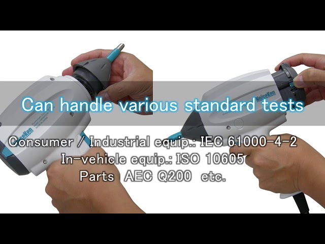
Electrostatic Discharge Simulator (ESS series)
EMC test equipment to evaluate the resistibility of electronic equipment when electrostatic charges on a human body or object has been discharged to the electronic equipment. This product can be used for evaluating performance degradation of any types of electronic products.
read more -

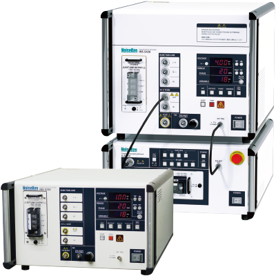
Impulse Noise Simulator (INS Series)
A simulator to reproduce fast rise-up noises which are generated when switching ON / OFF electric current on the inductive load. It can be used for performance evaluation of electronic equipment upon reproduction of line noises which are intruded to the power supply lines or induced noises onto the telecommunication lines.
read more -

Fast Transient Burst Simulator(FNS)
A simulator that simulate to reproduce fast-repeating high-frequency noise that occurs when switches are turned on and off. It's a noise immunity test for power supply lines and I / O signal lines that the international standard IEC 61000-4-4 requires, and it is one of the important tests adopted in JIS standard.
read more -

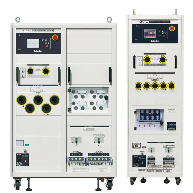
Lightning Surge Simulator (LSS)
A simulator to reproduce “High energy induced lightning noise” which is induced by potential change on the ground, or done to power lines or telephone lines as result of lightning current. This immunity test is required by major standards including IEC61000-4-5 and JEC 210/212 and is widely used in many industries.
read more -
Voltage Dip and Swell Simulator / Other Simulators
A simulator to reproduce voltage variation phenomena in commercial power supplies (AC100V/200V). This type of immunity test against voltage variation phenomena is defined in IEC 61000-4-11 and is widely used in many industries.
read more -
Damped Oscillatory Wave Simulator (SWCS)
This tester that simulates the fast-repeating, damped oscillation waveform noise that occurs when switching on/off a switch.
read more -
Automotive Transient Surge Simulator(ISS/JSS)
Simulator to reproduce various transient surge phenomena which are generated in vehicles and defined in the international standard ISO-7637-2 Standard for evaluating automotive electronics immunity. Please contact us for transient testers to perform testing to manufacturers' private standards.
read more -

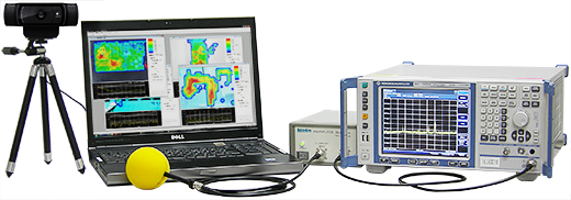
Emission Measurement Equipment (EPS)
Nowadays, components mountings are getting dense accompanied with miniaturization of electronics equipments. Emission Measurement System "EPS series" are efficient tools to measure such radiation noise on PCB in normal office environments and visualize the noise strength on a PC display.
read more -
Discontinued Products
We also conduct repairs and maintenance for the discontinued products.
read more


What are RF products and test systems?
RF test systems are aimed for evaluating the resistance of electronic devices to
the effects of electromagnetic waves from wireless communications such as televisions, radios and mobile phones.
It is also a measurement system for unwanted interference waves radiated from such equipment.
RF Products
-

RF Products
We offer antennas, LISNs, amplifiers, antenna masts, coaxial switches and other equipment used in various EMC test systems.
read more -

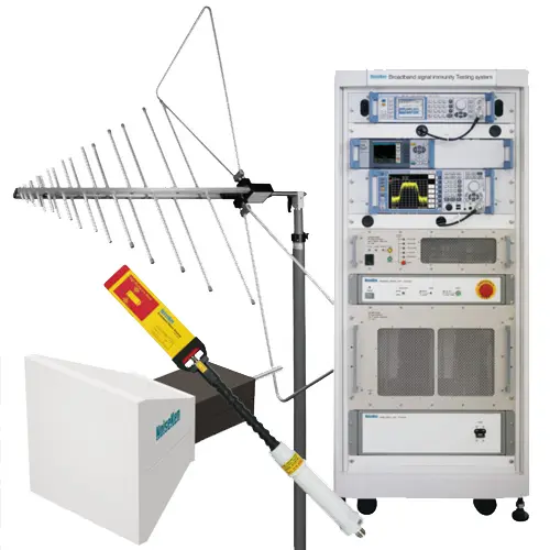
Immunity Testing System
The test systems for evaluating the resistance of electronic equipment to the effects of electromagnetic radiation from mobile phones and other wireless communications.
read more

News
Contact
Repair, Inspection and Calibration
Customer Service CenterNew Purchase Consultation, Materials Request
Product Inquiry Form